There are a lot of resin materials available on the market, all with different mechanical properties and prices. In contrast to FDM, where polymer filament is used from a known material with certain mechanical properties, SLA, DLP and LCD 3D printers use resin where mechanical properties are obtained by the chemical composition of the resin. Because of the difference in chemical composition of the resin, the mechanical properties (material characteristics) are very important and will help to compare different resins. Mechanical properties can help choose the right resin for your application. In many cases a 3D-printing resin suppliers provides a set of mechanical properties for each material. What do these mechanical properties mean and how do they relate to your application? This article will give an insight in the meaning of mechanical properties and answers questing regarding properties of 3D-printed resin parts.
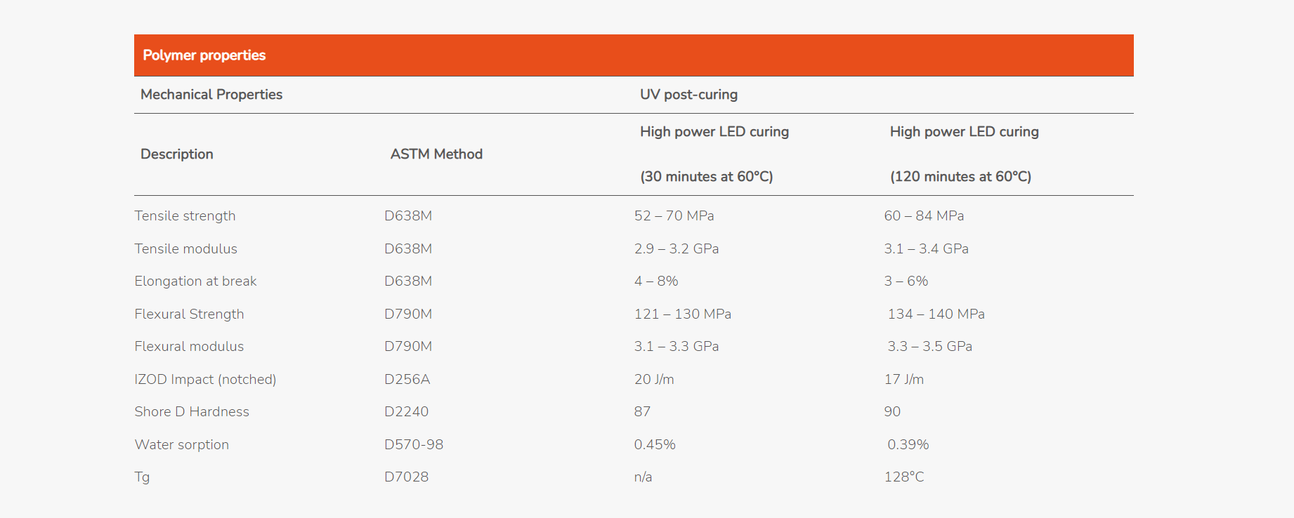
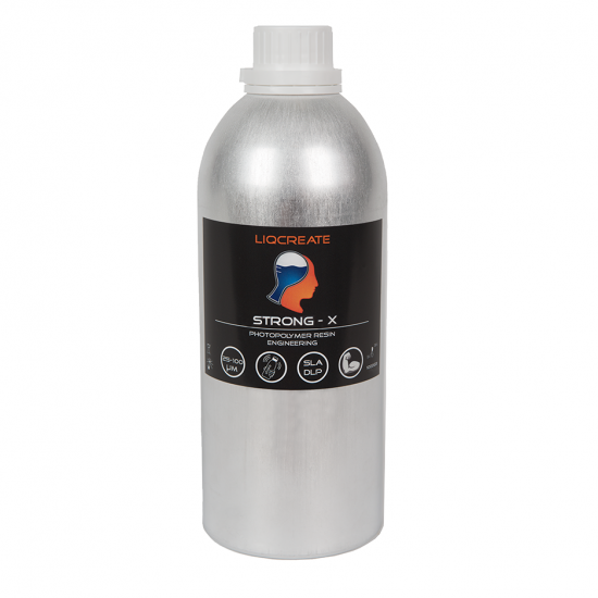
To explain the meaning of mechanical properties, the example of the technical data (from the TDS) of Liqcreate Strong-X is discussed. The table below will show the technical data of Liqcreate Strong-X:
Liquid properties of 3d-printing resin
The first part of the technical data of a material will tell more about the liquid properties. The appearance will give more information about the color and the physical state of the material. In case of resins, the physical state should always be liquid.
What are Ec and Dp values for 3D-printed resin?
All Liqcreate resins are UV-curable 3D-Printing resins, which means that they have a specified reactivity to light. This reactivity controls how the resin behaves in the printer. Specific parameters about its reactivity are the Critical Enegergy (Ec) and the Depth of Penetration (Dp), two values which can be found for all Liqcreate resin in their corresponding Technical Data Sheet. These two properties are empirically derived values based on measurements using a 3D-printer. These properties are wavelength dependant!
Reactivity to light is measured by exposing the resin with different doses of energy (exposure), in most cases this is controlled by increasing the exposure time in the 3D-printer. Then the layer thickness of the cured resin is measured and plotted versus the corresponding energy input as seen in the figure below.
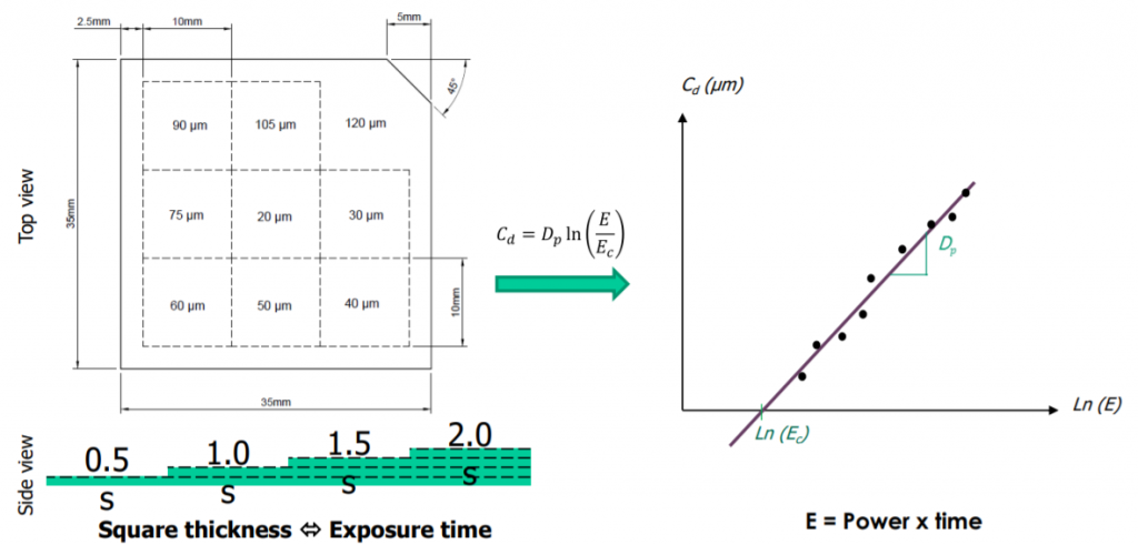
Because the resin will absorb the light and using part of the energy to start the polymerization reaction, the cure depth will always be finite, leading to a logarithmic correlation between the exposure and the cure depth, a typical curve is shown in the figure above. [10]
The curve (working curve) is a visual representation of the correlation between printer and resin and based on this a mathematical correlation is derived, as shown in formula 1 with:
Cd = Cure Depth [mm] (layer thickness)
Dp = Depth of penetration [mm] (slope of Cd vs LogExp)
Ec = Critical Energy [J/mm2] (the minimal amount of energy required to form a solid layer)
Cd = Dp • In(Exp) + Ec
And where Exp = exposure [J/m2], which is a function of the exposure time calculated as shown in formula 2, with:
t = Time [s] (illumination time)
Irr = Irradiance [W/m2] (power of the lightsource)
Exp = t • Irr
So far the technical part about the curing properties, but how do these parameter describe the behavior of resins in a 3D-printer from a more practical point of view?
The depth of penetration (Dp) shows a materials sensitivity to changes in light output, which means that a material with a lower Dp has better performance when subjected to variations in exposure time/light source power, while a material with a higher Dp, is more likely a faster printing material but also more sensitive for failure at deviations in light output. Whereas its seems that a faster printing resins is more preferable, a less sensitive resin is practical more useful, because of high likeliness in changes in light output due to lack of proper cleaning and degradation of the light source, especially for DLP units without auto-calibration.
The critical energy (Ec) is a value for the minimum amount of energy required to form a solid layer and therefor the minimum amount of energy required for 3D-printing.
These values are derived from practical measurements, which means that they can vary when the parameters within the measurement are changed like temperature and wavelength.
What other liquid properties are important for resin 3d-printing?
The viscosity and density of the material will give information about the liquid itself. A higher viscosity, means a thicker resin. This has an effect on the reflux of the resin and on the movements of the platform. Also cleaning a resin 3D-printed part is easier with lower viscous resin. If you know the volume of your 3D model and the density of the material you selected, you can easily calculate the weight of your 3D printed model.
Polymer properties of resin 3D-printed parts
After taking notice of the liquid properties, the next information will tell you more about the mechanical properties of the polymer. Mechanical properties are material properties that give an insight on how materials behave under specified types of mechanical stress. Many different types of stress can be applied to determine the mechanical properties, which can be generally divided in three types that are most commonly used in the polymer industry, tensile, compression and impact stress.
Tensile strength, young modulus and elongation
Tensile testing is used to measure a materials performance under linear tension stress, which in short means what happens if you pull on the material (3d-printed resin part). The test is performed by applying tension to a specified test specimen as seen in figure 1. Typically dog-bone shaped test specimen are used in which the wide parts are used for gripping the specimen and the forces are applied to the smaller part of the specimen.
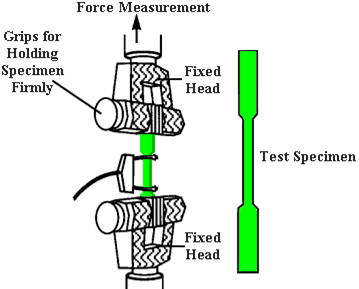
Figure 1: Testing mechanical properties in tensile direction.[1]
In this test the material is stretched until it breaks and during this process the amount of force is measured against the amount of strain applied to the specimen and plotted in a curve. A typical curve is shown in figure 2. These curves show the materials “behavior” and are used to determine a variety of mechanical properties.
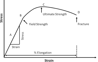 Figure 2: Typical Stress-strain curve for tensile testing with A: measure of the tensile modulus; B; Yield Strength; C: Tensile Strength and D: the maximum amount of strain before failure.[2]
All Liqcreate materials are tested this way to determine the following mechanical properties:
- Tensile Strength: The highest amount of stress before failure, measured as seen in Figure 2. Typically this means that material with a higher Tensile strength can withstand more force before breaking.
- Elongation at break: The amount the material is stretched as a percentage of the original length. Measured by the total amount of strain before failure.
- Young modulus: A measure of the stiffness of a material, a higher modulus means a more stiff material. The young modulus is measured by measuring the relation between stress and strain(slope) in the linear part of the curve.
How do tensile mechanical properties relate to your project?
In regard to the field of applications, tensile properties show characteristics for each material. Depending on which a choice can be made for the most suitable material. Typically brittle materials show very little strain but can handle high stress levels, which means that these material shown very little deformation when stress is applied and remain their shape and form until breakage. For softer/ flexible materials it shows that the total amount of stress they can handle is less because these deform when stress is applied but are less likely to break when limited strain is applied. In most materials it is a trade-off between strength/modulus and elongation. It is therefore important to know what the influence of each these properties have on your project.
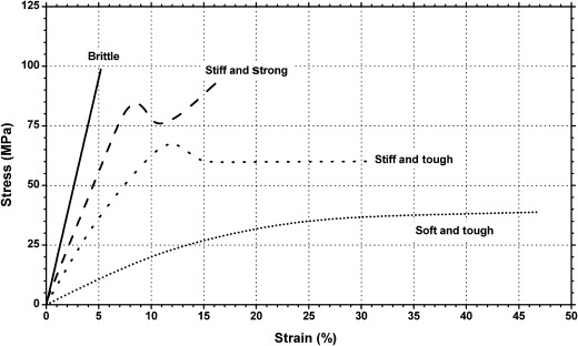
Figure 3: Behaviour of different types of materials during tensile testing.
Flexural strength and flexural modulus
Flexural strength and flexural modulus are generally tested on the same test equipment as the tensile properties. For this test a 3 point bending tests is performed. A rectangular sample is set on two fixture point and a load is applied in between these points in the opposite direction, a schematic view is shown in Figure 4.
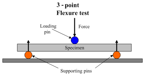
Figure 4: Schematic view of 3-point bending test.[3]
The deformation of the sample is measured against the force applied, leading to a similar curve as found with tensile testing. The main difference between flexural testing and tensile testing is that in tensile testing a linear stress is applied and in flexural testing a combination between tensile and compression forces are applied, showing a different behavior of the materials. This is shown in figure 4.
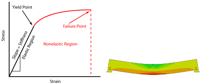
Figure 5: Left, typical flexural test curve; Right) heat map of applied stress during a 3-point bending test where in green the material is subjected to compression forces and in red the sample is subjected to tensile forces.[4]
This test is used in general to determine two mechanical properties:
- Flexural Strength: Highest amount of force the material can withstand before failure.
- Flexural Modulus: A measure of material stiffness, considered as a ration between applied force and deformation in the elastic region.
How do flexural properties relate to your project?
Flexural strength and flexural modulus can be important properties to select a material on for your project, especially when your project requires a material that perform well under compression forces. High strength and high modulus materials like Liqcreate Strong-X, with a flexural strength of 135 MPa and a flexural modulus of 3,25 GPa perform excellent under tension. The downside of these materials is often a lower elongation and impact, compared to the more flexible materials.
What does IZOD impact strength mean in relation with 3D-printed parts?
Izod Impact measurement is a method for measuring he impact resistance of a material. In this test an impact force is applied to a specified notched sample, as seen in figure 5 below, the size and shape of the sample is varied for different types of materials e.g. plastics, ceramics or metals. The impact force is applied by a hammer on a pendulum, where the impact force is determined by the high of the fall, the weight of the hammer and the length of the pendulum.[5][6]
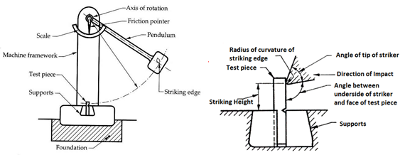
Figure 6: Schematic representation of the IZOD impact test.
In the Izod Impact test the amount of energy applied by the hammer is known and the amount of force absorbed by the material is measured. Therefor the impact resistance is the most common used method for testing the toughness of a resin material as toughness is defined as the ability of a material to absorb energy and plastically deform before failure.
There are a lot of resin materials available and for users often difficult to identify if a resin is useful for their project. For instance there are dozens of “ABS-like” resins available, but if you take a good look at their properties, some of the properties like elongation or strength match real ABS plastic. The most important property, the impact strength is often just 10% of the impact strength of ABS.
What are thermal properties of a 3D-printed part?
To determine how materials behave under changes in temperature, a variety of thermal tests can be performed. The primary property which is investigated during these tests is the Glass Transition Temperature or Tg. The Tg is a defined temperature at which a material will change from a glassy state to a rubbery state. Even though the Tg is always defined as a single temperature the glass transition occurs over a longer temperature range which differs for every material.
There are different ways to measure the Tg, the most common used method applied to thermoplastics is by Differential Scanning Calorimetry (DSC). For Thermoset plastics, which typically all UV-curable 3D-printing resins are, Dynamic Mechanical Analysis (DMA) is most commonly used.
Tg measurement using DSC method
Differential Scanning Calorimetry is a thermo-analytical technique which heats and cools samples at a specified rate and measures the amount of energy required for the temperature changes. Any phase change in a sample will either cost or produce energy showing a difference in the amount of energy required for heating the system. The consumed energy is then plotted versus the temperature showing all exothermic and endothermic changes that occur.
Tg measurement using DMA method
Typically 3D-printing resin material is a crosslinked polymers and therefor show only slight thermal changes during the glass transition, making it quit difficult to measure Tg using DSC. As an alternative, Dynamic Mechanical Analysis can be used. DMA uses mechanical measurement and plots the data versus the temperature. Many different measurements can be used like compressive, tensile, flexural, or shear-stress. The stress is applied repeatedly and for each measurement a modulus is measured while temperature changes are applied. A typical DMA curve is shown in figure 6. The region in where the modulus suddenly drops is considered the glass transition.[7]
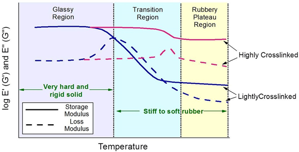
Figure 7: Loss and storage modulus of crosslinked material during a DMA measurement.
Heat Deflection Temperature (HDT)
The Heat Deflection Temperature is the temperature under which a material deforms at a specified load. This test is performed in a 3-point bending setup as shown in figure 7. The sample 3D-printed resin test-bar is subjected to a constant force of either 0.455 MPa or 1.82 MPa at which point the temperature in increased at a specified rate of 2°C/min. The temperature at which a deformation of 0.25mm is measured is called the HDT.
Even though the test result are not directly applicable it is mainly used as a universally comparison tool to check the thermal performance of different material.[8]
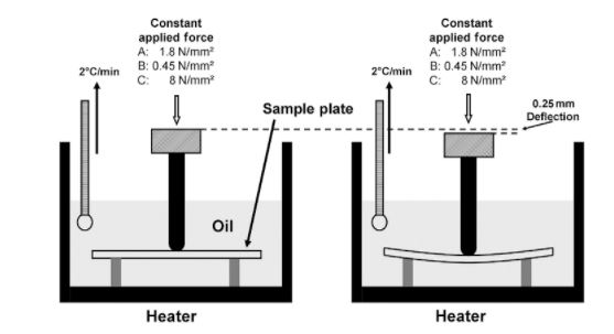
Figure 8: Schematic representation of heat deflection temperature test.
What does Shore D hardness mean?
Shore D hardness is a simple test, which measures the resistance of a material to indentation at the surface. This test is performed by pressing a specified needle with a specified force into the surface of the test material. This test is mainly used in the rubber industry and shows an indication about the rigidity of the rubber or 3D-printed resin material. In the plastic industry this test is not very interesting, since the Shore values show no direct correlation to any mechanical properties and are merely used as a fast and simple method in quality control. All hard material are in the region of a Shore D of 80-90. Figure 9 shows an overview of the shore A and Shore D hardness scale with examples[9]. Compared to the Liqcreate TDS of Strong-X, with a Shore D of 87 it is classified as a hard material, just as all the other rigid Liqcreate materials with a Shore D of ~82.

Figure 9: Shore A and Shore D hardness scale with material examples.[7]
How is water absorption measured and how does this effect your project?
Water absorption is measured according to ASTM D570-98. This test method for rate of water absorption serves as a guide to the proportion of water absorbed by a material or 3D-printed resin part. In the test, the test resin is 3d-printed in the form of a disk 50.8 mm in diameter and 3.2 mm in thickness. Weight of the material is recorded before and after 24 hour immersion in demineralized water at 23 degree celcius.
Water absorption can have a great influence on 3D-printed resin part when used in moisture or wet environment. Generally mechanical properties are decreasing when a polymer material is fully saturated with water and the polymer resin material might swell when it has a high water absorption. It is important to select a resin with low water absorption, like Liqcreate Strong-X or Deep Blue when using 3D-printed resin parts in these conditions.
[1] http://www.matweb.com/reference/tensilestrength.aspx
[3] www.subtech.com
[4] https://www.fictiv.com/hwg/design/engineering-fundamentals-refresh-strength-vs-stiffness-vs-hardness
[6] http://sm-nitk.vlabs.ac.in/exp5/index.html
[9] https://www.smooth-on.com/page/durometer-shore-hardness-scale/
[10] https://www.radtech2017.com/wp-content/uploads/2017/11/92Bonhoure.pdf
